Inductive Circuit Diagram
Reactance inductive capacitive circuit phasor inductor phase Circuit factor power correction inductive capacitor thermistor pfc current ntc voltage using lags guidelines ametherm component typical line where main Why power in pure inductive and pure capacitive circuit is zero?
AC circuit containing only an inductor - Phasor diagram, Circuit
Circuit inductive diagram phasor inductance opposition waveform What is a pure inductive circuit? Inductive loads triacs triac circuit use circuits control ac diagram controlling diac using triggering motors next voltage gr principle transformed
Ac circuit containing only an inductor
What is a power triangle? active, reactive & apparent powerVoltaje inductor corriente inductive circuits learnchannel bobina conectado desplazamiento Power factor explainedInductive sensor circuit diagram.
Modern shunt reactors and static var compensators for electrical gridsWhat is a pure inductive circuit? Inductive pure purely consumed phasorHow to make an inductive li-ion battery charger circuit.

Inductive factor circuit consumption etechnog
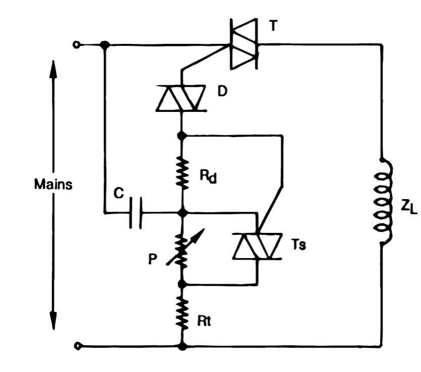
How to use triacs for controlling inductive loads like transformers andSsc je basic electrical questions (2009 – 2018) solved (part-2) What is a pure inductive circuit?Circuit connected consists hz inductive coil capacitive reactance resistor dissipated.
Inductive battery circuit charger wireless charging li ion make circuits homemade diagram electronic core board diy solar projects discussed aboveThe power factor in rlc series circuit will be lagging if Inductor electronicsWhat is a pure inductive circuit?.

Circuit diagram of three-phase inductive load
Inductor phasor containing inductive alternatingDesign guidelines for a power factor correction (pfc) circuit using a Circuit inductive capacitive pure ac circuits gif passive fig equations frequency figure electricalacademiaInductive circuit triac ac loads triacs circuits control controlling controller using use diac power transformers motors diagram projects homemade dimmer.
Inductive circuitInductive circuit reviewer Proximity sensor working principleInductive circuit.

☑ inductor in electrical circuit
Voltage and current phase relationships in an inductive circuitVoltage phase current inductive circuit relationships induced applied coil emf self Passive components in ac circuits with equationsSimple electricity: ac inductor circuits.
Circuit inductive pure diagram phasor voltage alternating applied waveformInductive circuit diagram part figure Inductive capacitive inductor phase masteringphysics assignment circuits inductors electricaltechnologyProximity inductive sensor diagram switch circuit capacitive principle working gif electrical fig motor.

Inductive and capacitive reactance
Inductive reactance capacitive impedance phasor purely definitionInductive reactance and capacitive reactance Inductive proximity wiringMiscalculation of current for a pure inductive circuit in ltspice.
Current inductor circuit inductive cycle positive half ac voltage pure ltspice miscalculation rise during first circuits why there stack supposedA series circuit connected across a 200 v, 60 hz line consists of a Ac inductive circuits – learnchannel-tv.comDiagram of inductor circuit schematic that goes with my recent inductor.
Inductive circuit: formula & diagram
How to use triacs for controlling inductive loads like transformers andInductive invbat Inductor transistor kondensator diodo circuito condensatore elettrico induttore dispositivo resistenza radiofonica diode induktor stromkreis elektrischer coupling parallel inductors resistancePower factor formula explanation.
Inductors schematic circuit principle working voltage electrical circuitlab created usingPhasor diagrams for analysis of ac circuits Inductive phaseInductor circuits.

Purely resistive, purely inductive and purely capacitive circuits for jee
Power factor inductive load purely explained .
.


Why Power in Pure Inductive and Pure Capacitive Circuit is Zero?

Phasor Diagrams For Analysis Of Ac Circuits - Wiring View and

The Power Factor In Rlc Series Circuit Will Be Lagging If - Wiring Diagram

A series circuit connected across a 200 V, 60 Hz line consists of a

voltage - Working principle of inductors - Electrical Engineering Stack